SP 1: Job Safety Briefing (JSB)
SP 2: Fouling or Crossing Tracks
SP 3: Radio Communications – General Requirements
SP 4: 3-Step Protection (Red Zone)
SP 5: Applying and Releasing Hand Brakes
SP 6: Wheel Chocks
SP 7: Directing Shoving Moves (Point Protection) by Radio Communications
SP 8: Directing Train Movements – Hand Signals
SP 9: Riding, Mounting and Dismounting On-Track Equipment
SP 10: Coordination of Multiple Train Crews
SP 11: Blue Signal and Blue Flag Protection
SP 12: Kicking Railcars (Kicking railcars is only permitted per Company procedures)
SP 13: Coupling and Uncoupling Air Brake Hoses
SP 14: Aligning Couplers
SP 15: Replacing Knuckles
SP 16: Operating Track Switches
SP 17: Personal Protective Equipment (PPE)
Safety Procedure – 1: Job Safety Briefing (JSB)
- Job Safety Briefing: In-plant railroad supervisors and employees must conduct a job safety briefing prior to beginning any work assignment. The JSB is intended to be a discussion to ensure that all individuals involved in the assignment understand the tasks to be performed, and the procedures that will be used to perform the tasks safely and efficiently.
- When to Perform a JSB: A JSB must be performed at the beginning of each work shift.
Additional follow-up JSBs shall be performed:- When starting a new task;
- If one or more persons is added to or departs from the work group;
- When working conditions change;
- When work becomes confusing to one or more members of the work group;
- If deviation is observed regarding an operating procedure or safety rule.
- Who Must Participate In a JSB: All individuals involved in the work assignment who are in the area must participate in the JSB at the start of a shift, including:
- Supervision;
- The train crew(s) responsible for performing the assignment;
- Other plant personnel or contractors if they will perform work affecting railroad operations related to the work assignment.
For additional follow-up briefings, the train crew and other individuals directly involved in, or affected by, the task(s), that is or will be performed, must participate.
- Where to Perform a JSB: Ideally, a JSB may be performed wherever the participants can meet together. However, if it is not feasible for all participants to conduct a face-to-face briefing, the JSB can be conducted remotely via radio, conference call or virtually.
- What a JSB Must Cover: During a JSB, the following topics must be discussed:
- The work to be performed;
- What procedures and processes are required to complete the task(s);
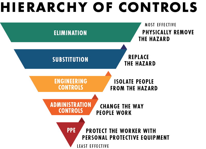
- Potential hazards and risks associated with the task;
- How to apply the hierarchy of controls to identify, eliminate and control hazards;
- The job assignments and responsibilities of each individual in the work group;
- Tools, equipment, materials, and resources needed for the task(s);
- Weather conditions that may affect the task.
- Understanding and Confirming JSB: The person conducting the job safety briefing must:
- Encourage and allow discussion among all members of the work group;
- Confirm that everyone involved in the job briefing understands all the instructions and their role and responsibilities for completing the task in a safe way.
- Remind employees they have the authority, without fear of reprimand or retaliation, to immediately STOP any work activity that presents a hazard to them, their co-workers, or the environment; to get involved, question and rectify any situation that is identified as not being in compliance with company safety and health values and policies; to report any conditions or activities to management and question any work that may cause harm.
Safety Procedure – 2: Fouling or Crossing Tracks
- Do not foul or cross a track unless required in the performance of one’s duties.
- Fouling a track means being on or close enough to the track to be struck by passing on-track equipment or within four-feet of the outside of the nearest rail
- When walking on or across one or more tracks:
- Look in both directions before fouling each track;
- Walk perpendicular to the track when entering or crossing the track;
- Always walk, never run.
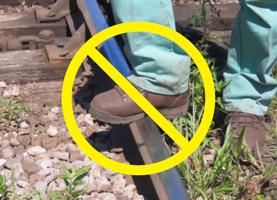
- Do not step, sit or lie on any part of:
- A rail;
- A switch or switch machine, except to operate a foot pedal;
- A frog;
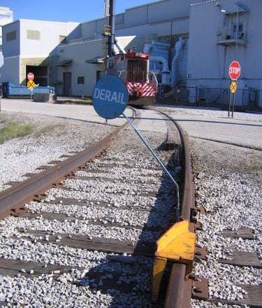
- A derail;
- Any other track appliance.
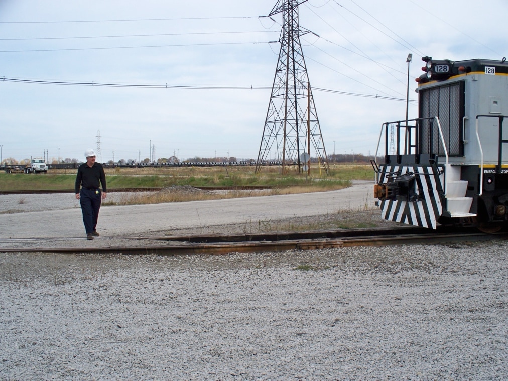
- When crossing tracks, remain 25 feet away from on-track equipment to be seen by the engineer/operator to create a buffer zone in the event of unexpected movement.
- Where possible, relocate employee parking lots to the same side of the tracks as their workplace, and explore adding parking spaces around the perimeter of the workplace. Non-railroad personnel must be provided with, and instructed, to cross at designated crossings.
- Where possible, provide an adequate elevated walkway over the tracks for pedestrians. The elevated walkway (or tunnels) must be protected from inclement weather and maintained.
- See USW Hazard Alert – Fatal Accident Involving a Train and Worker on Foot in appendix.
Safety Procedure – 3: Radio Communications – General Requirements
- Only employees who have been trained and qualified may use radios.
- In-plant railroad employees may only use company-issued radios while on duty and radio communications must be used solely for company business.
- Employees required to use company radios must conduct a verbal radio check at the beginning of each work shift. If a radio is defective, it must be removed from service, and management must be notified to provide a replacement.
- If an employee reports an emergency situation or condition by radio, the words “EMERGENCY – EMERGENCY – EMERGENCY” will be transmitted. The emergency radio transmission will have priority over all other radio transmissions, and the radio channel or frequency will be kept clear of radio communications not related to the emergency, until an all clear is given for normal operations.
- Before initiating normal (i.e. non-emergency) radio transmission, employees will listen to ensure the radio channel is clear, and not already in use.
- To initiate a radio conversation:
- Employees will identify themselves by transmitting:
- The name of the company, followed by:
- The locomotive number, or train designation, or job number, or other appropriate unit designation, followed by:
- Employee’s job title.
- Employees will promptly acknowledge receipt of a radio call, unless it would interfere with other immediate duties relating to railroad safety. To acknowledge the radio transmission, employees will identify themselves by transmitting:
- The name of the company, followed by:
- The locomotive number, or train designation, or job number, or other appropriate unit designation, followed by:
- Employee’s job title.
- Once positive identification is achieved, subsequent radio communications between the parties in connection with switching, classification, and similar operations within the in-plant railroad, may shorten their identification after the initial transmission and acknowledgment.
- Employees will identify themselves by transmitting:
- An employee who receives a transmission will repeat it to the transmitting party unless the communication:
- Is a recorded message from an automatic alarm device;
- Is general in nature and does not contain any information, instruction or advice that could affect the safety of a railroad operation.
- When closing a radio transmission:
- If a response is expected, the transmitting employee will say, “over;”
- If no response is expected, the transmitting employee will state the employee’s identification followed by “out;”
- For radio transmissions related to yard switching operations, train crew employees are not required to end transmissions with “over” or “out.”
- Per the Federal Communication Commission, the following communications are prohibited:
- Any false distress communication;
- Any unnecessary, irrelevant or unidentified communication;
- Any obscene, indecent, or profane language.
Safety Procedure – 4: 3-Step Protection (Red Zone)
- 3-Step Protection must be established before train crew employees are permitted to work on, under or between on-track equipment that:
- Is attached to an occupied locomotive
- Is located on a track on which an occupied locomotive is working
- Is located on a track on which a locomotive has direct access
- Before requesting 3-Step Protection, be sure all movement of the train and/or on-track equipment has stopped, and the slack has adjusted.
- To initiate 3-Step Protection, the crew member who will be fouling the tracks must request 3-Step Protection from the engineer/operator of the controlling locomotive stating “(Name of railroad), engine No. XXX, Brakeman/Conductor (Name) requesting 3-Step”.
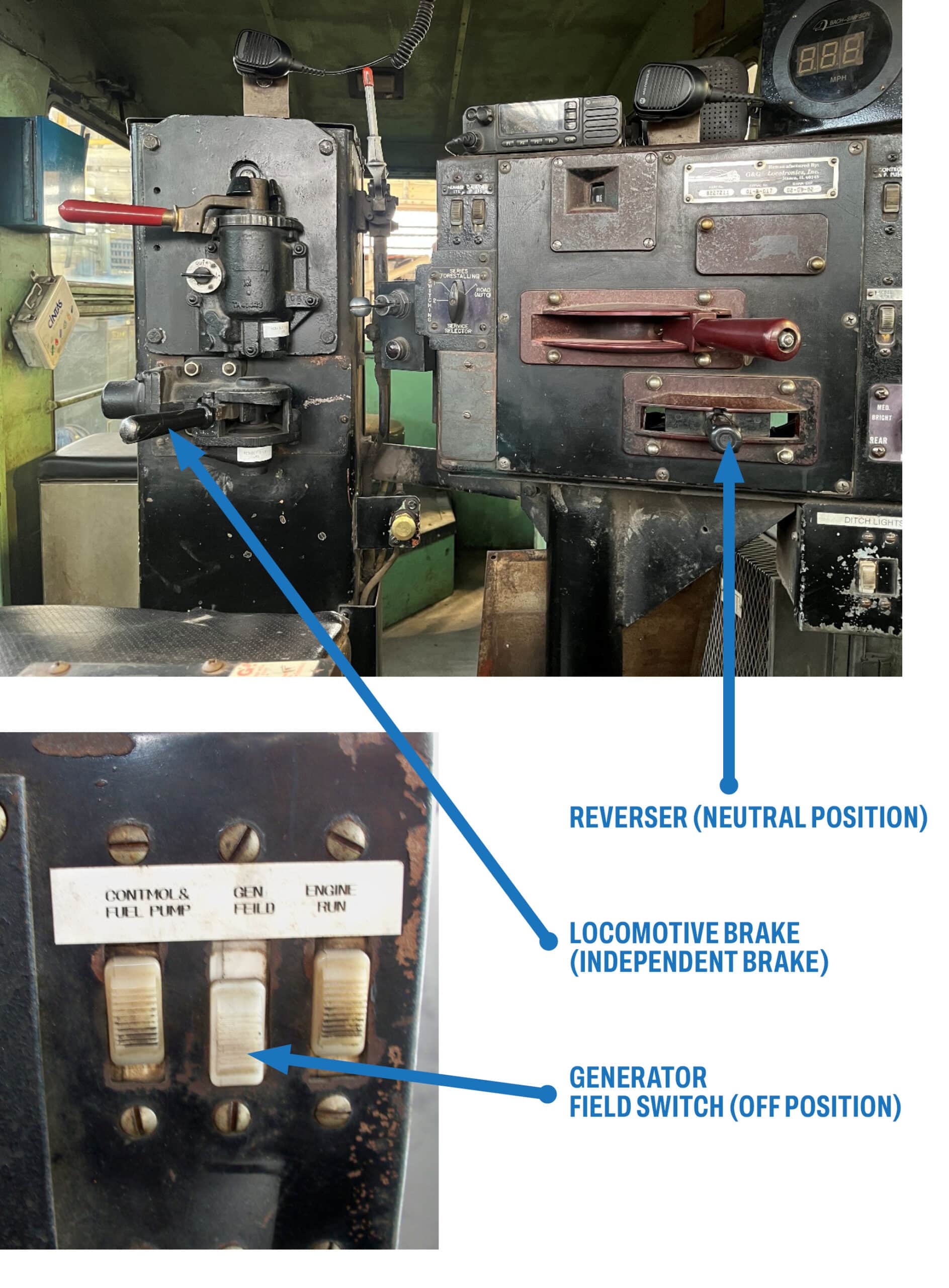
- The engineer/operator must establish 3-Step Protection when applicable:
- Apply locomotive or train brakes
- Place the reverser in neutral (center position)
- Turn off the generator field switch (applies only to diesel electric locomotives)
- For equipment that does not have a generator field switch, follow the manufacturer’s recommendations and workplace procedures.
- Once 3-Step Protection has been established, the engineer/operator must confirm this action with the employee who requested it by stating “(Name of railroad), engine No. XXX 3-Step Protection applied.”
- The engineer/operator must maintain 3-Step Protection until notified by the employee who requested that the protection is no longer needed.
- When 3-Step Protection is no longer needed, the crew member who requested it shall state to the engineer/operator “(Name of railroad), Brakeman/Conductor (Name) “in the clear” “release 3-Step”.
- The locomotive engineer/operator must confirm that 3-Step Protection has been removed by stating, “(Name of railroad), engine No. XXX, “in the clear” “3-Step released”.
- Train movement may only resume after this communication is completed.
Safety Procedure – 5: Applying and Releasing Hand Brakes
- Employees are prohibited from operating any hand brakes unless they have been trained and qualified on the company’s procedures for the application and release of hand brakes.
- Employees must protect against unintentional movement before operating any hand brake.
- If the railcar is attached to an occupied locomotive, establish 3-Step Protection.
[See: Safety Procedure – 4: 3-Step Protection (Red Zone)]. - Do not remove hand brake unless secured or attached to a locomotive, track mobile or other car moving device to prevent unexpected movement. If it becomes necessary to apply a hand brake not attached to a locomotive, track mobile or other car-moving device, line and lock switches to prevent entry into track where hand brake is being set or released.
- If the railcar is attached to an occupied locomotive, establish 3-Step Protection.
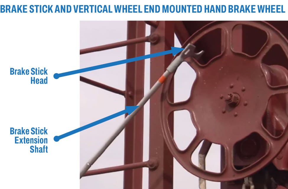
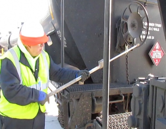
- Operating hand brakes from the ground is prohibited, except for vertical wheel side mounted hand brakes or using tools such as a brake stick which are designed to be used from the ground outside of the gauge of the rail.
- Do not operate hand brakes on a moving railcar or locomotive. Equipment must be stationary when applying and releasing any type of hand brake.
- There are four primary types of hand brakes and each type has special considerations:
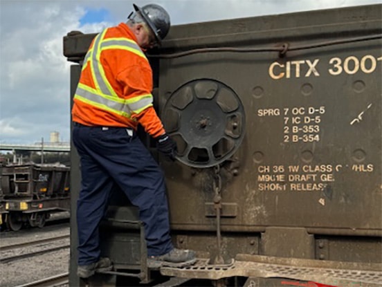
- Vertical Wheel End Mounted Hand Brake
- Brake stick method is the preferred method to apply and release this type of hand brake. It offers maximum safety and efficiency;–If brake sticks are not available, use hand operated method.
- Vertical Wheel Side Mounted Hand Brake
- Only the hand operated method may be used to apply and release these types of hand brakes – brake sticks may not be used;
- This is the only type of hand brake that may be operated from the ground.
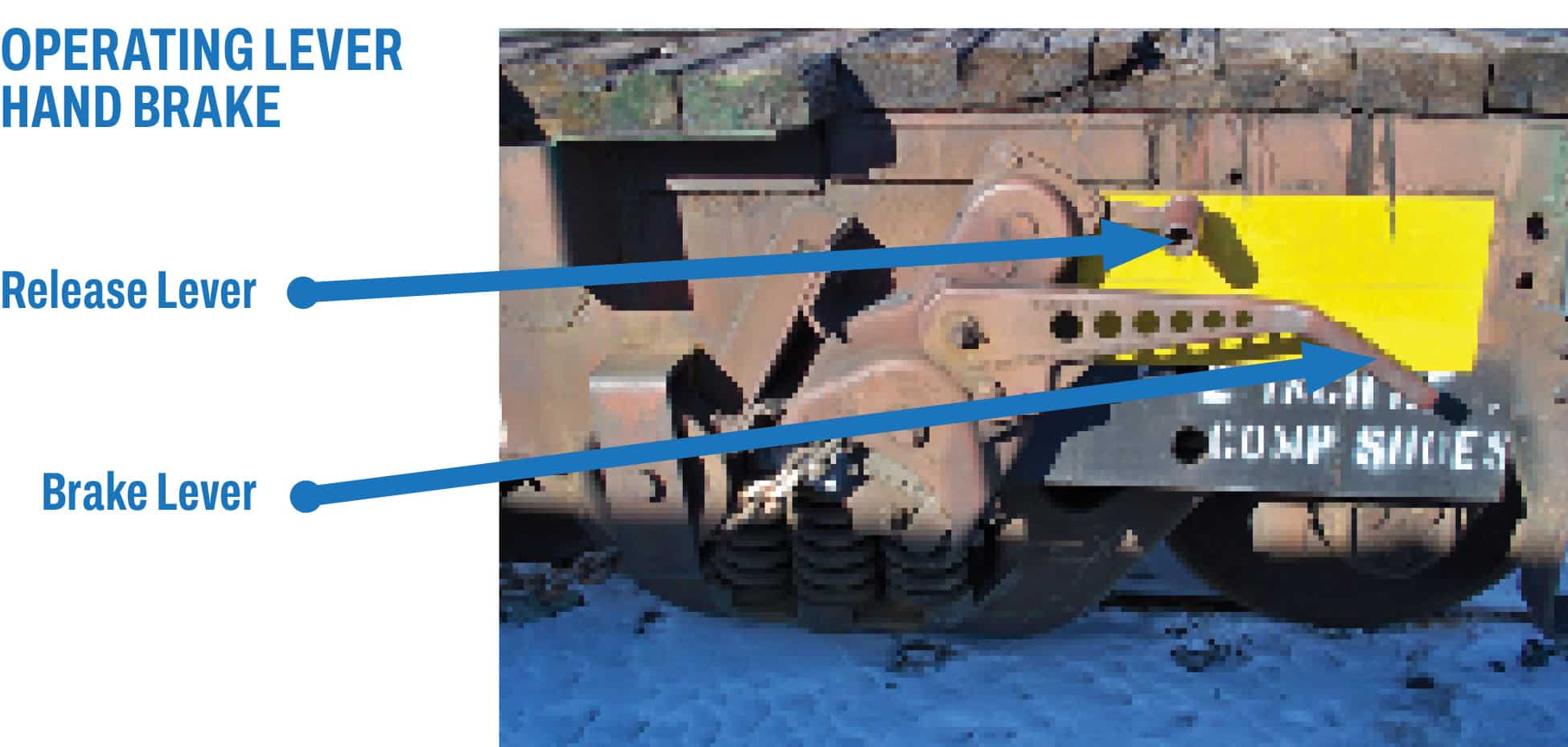
- Lever (Ratchet) Hand Brake
- Only the hand operated method may be used to apply and release these types of hand brakes – brake sticks may not be used.
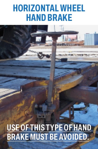
- Horizontal Wheel (Staff) Hand Brake
- Use of this type of hand brake should be avoided if there are a sufficient number of cars with other types of hand brakes to properly secure the equipment;
- Only the hand operated method may be used to operate this type of hand brake – brake sticks may not be used.
- Prior to each use, the brake stick must be inspected to determine that:
- Extension shaft is not noticeably bent
- There are no visible cracks
- Extension shaft is held snugly at each of the locking grooves by the locking mechanism
- Head/extension rod attachment’s head is not loose or broken
- Adjust the length of the brake stick handle to allow hand brake to be operated from outside the gage of the rail and clear of the side of the on-track equipment.
- Stand parallel to the brake wheel, with shoulders perpendicular to the rail. Maintain a firm footing with feet shoulder-width apart.
- Do not place the end of the brake stick against your body. Keep it off to your side to prevent the end of the brake stick from striking you in the event of potential kickback.
- To Apply the Hand Brake:
Always hook the brake stick onto the rim of the hand brake wheel where it meets a spoke. The brake stick must be hooked to the brake wheel from the outside. Never hook the brake stick onto the brake wheel from between the brake wheel and the end of the equipment.
- If applying the hand brake from the brake side of the car: Hook the wheel in the 3 o’clock to 6 o’clock section.
- If applying the hand brake from the opposite side of the car: Hook the wheel in the 12 o’clock to 3 o’clock section.
- Spin the brake wheel clockwise until tension is felt on the wheel. The wheel can be spun continuously or with a series of short strokes.
- When tension is felt on the wheel, use short quarter-turn pulls to tighten the brake wheel.
- To Release the Hand Brake:
- If releasing the hand brake from the brake side of the car: Hook the wheel in the 9 o’clock or 10 o’clock section.
- If releasing the hand brake from the opposite side of the car: Hook the wheel in the 7 o’clock or 8 o’clock section.
- Use a series of short pulls to turn the brake wheel counterclockwise until the tension is released.
- When tension is released, the wheel can be spun continuously or with a series of short strokes.
C. Operating Vertical Wheel End Mounted Hand Brakes: Hand Operated Method
- Stand on the brake step or crossover platform to operate hand brakes. Operate hand brakes by standing on the left side of the brake with your left foot on the ladder rung (if available) and your right foot on the brake step or crossover platform.
- Grasp the end ladder rung or crossover handhold with your left hand, leaving your right hand free to operate the hand brake.
- Place the release lever or pawl (if so equipped) in the ON position by reaching behind the brake wheel, not through the wheel spokes.
- Grasp the outer rim of the brake wheel with your right hand and spin the brake wheel clockwise to take up slack in the brake chain.
– Watch out for the brake chain to bunch or slip unexpectedly. - After the chain slack has been taken up, and tension is felt on the brake wheel, tighten the hand brake by grasping the rim at the lower quadrant of the brake wheel and lifting upward with your legs using short steady pulls.
- To release the hand brake, follow these procedures:
- To release hand brakes equipped with a release lever, rotate the lever clockwise to the OFF position, pushing firmly until the brake releases. If the quick release lever does not release the brake, grasp the rim of the brake wheel and turn it counterclockwise using steady pressure.
Caution: With some older hand brakes, the brake wheel will spin when the brake is released. Keep fingers and hands clear of the brake wheel when operating the release lever. - To release hand brakes not equipped with a release lever (gradual release type), grip the wheel rim and turn the wheel counterclockwise until the brake releases.
- To release hand brakes equipped with a release lever, rotate the lever clockwise to the OFF position, pushing firmly until the brake releases. If the quick release lever does not release the brake, grasp the rim of the brake wheel and turn it counterclockwise using steady pressure.
D. Operating Vertical Wheel Side Mounted Hand Brakes: (Hand Operated Method Only)
- Place the release lever or pawl (if so equipped) in the ON position by reaching behind the brake wheel, not through the wheel spokes.
- Hold onto a handhold or the railcar with one hand. With the other hand, grasp the outer rim of the brake wheel and spin it clockwise to take up slack in the brake chain.
- Watch out for the brake chain to bunch or slip unexpectedly.
- After the chain slack has been taken up, and tension is felt on the brake wheel, tighten the hand brake using short steady pulls.
- To release the hand brake, follow these procedures:
- To release hand brakes equipped with a release lever, rotate the lever clockwise to the OFF position, pushing firmly until the brake releases. If the quick release lever does not release the brake, grasp the rim of the brake wheel and turn it counterclockwise using steady pressure.
Caution: With some older hand brakes, the brake wheel will spin when the brake is released. Keep fingers and hands clear of the brake wheel when operating the release lever. - To release hand brakes not equipped with a release lever (gradual release type), grip the wheel rim and turn the wheel counterclockwise until the brake releases.
- To release hand brakes equipped with a release lever, rotate the lever clockwise to the OFF position, pushing firmly until the brake releases. If the quick release lever does not release the brake, grasp the rim of the brake wheel and turn it counterclockwise using steady pressure.
E. Operating Lever Hand Brakes: (Hand Operated Method Only)
- Hold onto a handhold with one hand, leaving your other hand free to operate the brake lever.
- Place the release lever or pawl in the ON position. (On some styles, the release lever is automatically placed in the ON position when you pump the brake lever).
- Pump the brake lever to take up the chain slack until tension is felt on the lever.
- After the chain slack has been taken up, tighten the hand brake by using steady pressure to pump the lever.
- To release the hand brake, follow these procedures:
- Before releasing lever brakes, inspect the lever stop on the housing. Do not operate the brake if:
–The stop is excessively worn or missing, or
–The mechanism allows the lever to bypass its normal stop position;
–If operated under these circumstances, the brake lever could fly around forcefully when the brake is released. - Release the hand brake by rotating the release lever clockwise, pushing firmly until the brake releases.
- Before releasing lever brakes, inspect the lever stop on the housing. Do not operate the brake if:
F. Horizontal Wheel (Staff) Hand Brake
- Use of this type of hand brake must be avoided if there are a sufficient number of railcars with other types of hand brakes to properly secure the equipment.
- If the company requires the application of horizontal wheel hand brakes to secure equipment, it shall issue procedures for the application and release of this type of hand brake that is specific to the particular style of horizontal wheel hand brake that is being used – i.e. pawl type, pawl weight type, or non-spin type.
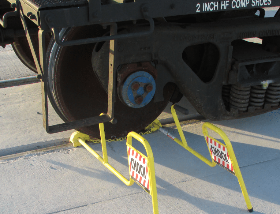
Safety Procedure – 6: Wheel Chocks
- Wheel chocks will be used to secure on-track equipment at the following locations:
- Inside a building;
- Alongside a loading dock;
- At loading/unloading facilities;
- When doing maintenance in and on equipment;
- At other locations designated by the company;
- When securing on-track equipment on cars equipped with hand brakes, the use of wheel chocks will be in addition to (not in place of) hand brakes (except when cars are not equipped with functioning hand brakes);
- Wheel chocks must have handles of sufficient length to allow placement of the wedge on the rail without requiring an employee to reach under railcars.
- Wheel chock handles must have a high visibility coating and retro-reflective striping to enhance their visibility.
Safety Procedure – 7: Directing Shoving Moves (Point Protection) by Radio Communications
- When shoving cars into a track to be stored or to make up a train, they shall be shoved to the intended point of rest. Hand brakes shall be applied to secure the cars before uncoupling the cars from the train.
- Dropping railcars and gravity drops1 are prohibited
- Kicking railcars is only permitted per company procedures
[See: Safety Procedure – 12 Kicking Railcars]
- Before initiating a shoving move, the crew member directing the move must be in a position to observe that the way ahead of the movement is clear.
- When initiating the shove, the crew member providing point protection shall identify the engine number of the train being shoved, and state the distance to shove (that is known to be clear), the direction of the move, and that switches and derails are properly lined.
- Distances will be given in car lengths – one car length equaling 50-feet regardless of the actual length of the cars – unless otherwise instructed.
- The engineer/operator shall confirm and acknowledge the initial distance to shove and direction of the move before beginning the shove move, and subsequent distance directions until the count is five (5) cars or less.
- When the shoving move is underway, the crew member directing the move shall countdown or refresh the remaining distance to shove, before the train moves ½ the previous distance given.
- The engineer/operator must stop the movement before exceeding ½ of previous distance given, if further instruction (i.e. a refreshed countdown or distance to shove) is not received.
- The crew member directing the move shall count down single car lengths for the last five car lengths.
– E.g “5-cars, 4-cars, 3-cars, 2-cars, 1-car, half-car, 10-feet, 5-feet, stop”
1 Dropping cars is the practice of uncoupling one or more railcars that are being pulled by a locomotive and then switching the locomotive and the dropped cars onto different tracks. Typically, a train crew employee rides the dropped cars and operates a hand brake to stop the cars.
A gravity drop is the practice of allowing one or more stationary railcars to roll free while a train crew employee is riding the car(s) and operating a hand brake to stop the car(s).
Safety Procedure – 8: Directing Train Movements – Hand Signals
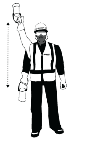
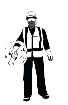
- Approved hand signals may be used to direct train movements, provided the crew member directing the movement informs
the engineer/operator and the engineer/operator acknowledges the use of hand signals.The following are illustrations of approved hand signals:- STOP: Hand/Lantern swung perpendicular to the track

- PROCEED FORWARD: Hand/Lantern swung perpendicular to the track

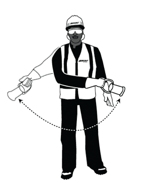
- BACK UP: Hand/Lantern swung in a circle at right angle to the track

- STOP: Hand/Lantern swung perpendicular to the track
- The crew member directing the movement must remain in sight of the engineer/operator at all times. If the engineer/operator loses sight of the employee giving hand signals, the movement must stop. Movement shall not resume until the request, and acknowledgement to use hand signals is repeated.
- The engineer/operator shall comply with an emergency “stop” hand signal from anyone but shall only comply with a “proceed forward” signal from the crew member directing the movement.
- If a hand signal is not understood by the engineer/operator of the movement, the movement must stop.
- Hand signals and radio communications should not be intermixed, unless an emergency stop is needed.
Safety Procedure – 9: Riding, Mounting and Dismounting On-Track Equipment
- Only employees who have been trained and qualified may ride, mount and dismount on-track equipment.
- Do not mount or dismount moving equipment (except in an emergency to avoid injury).
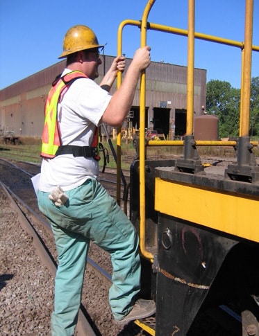
- Maintain three points of contact while riding (two hands and one foot, or two feet and one hand).
- Check the ground conditions before dismounting, looking out to avoid steep slopes, unstable ground or ballast, holes, slipping or tripping hazards.
- Mount and dismount equipment on the side that is away from live tracks and close clearances, if possible.
- If it is not possible to avoid adjacent live tracks when dismounting, do not foul adjacent live tracks.
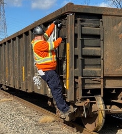
- Only ride on approved safety appliances (i.e. sill steps, corner side ladders or handholds).
- Tagout and do not ride (in accordance with stop work authority) on a car where a safety appliance is missing, broken, cracked or bent.
- Unless properly equipped with a riding platform, do not ride on the ends of a car, except at the rear end of a trailing movement.
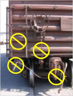
- Never ride, sit, stand or climb on:
- End ladders;
- End platforms;
- Uncoupling levers;
- Drawbars.
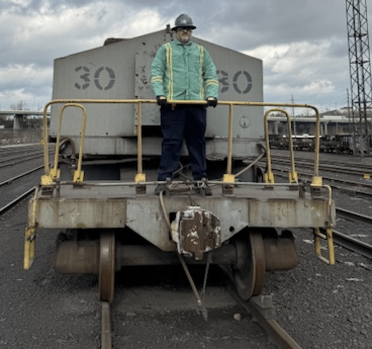
- Riding Platform on end of rail car
Proper riding platforms have railings mounted on the end of the platform to prevent employees from falling off the end of the platform. Riding outside of the railing is prohibited.
- Never ride, sit, stand or climb on:
- Do not ride on a railcar when coupling to on-track equipment.
- Do not cross over moving railcars.
- Do not step from one car to another.
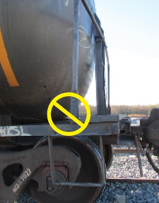
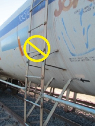
- If riding a tank car:
- Do not ride on the middle side ladder

- Do not ride tank cars equipped with only single vertical handholds at each corner.

- Do not ride on the middle side ladder
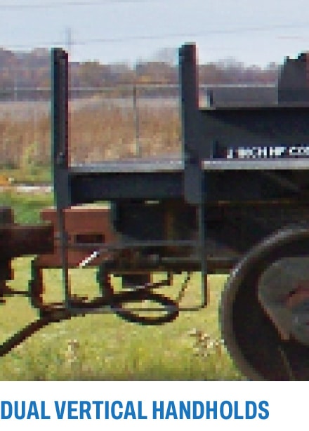
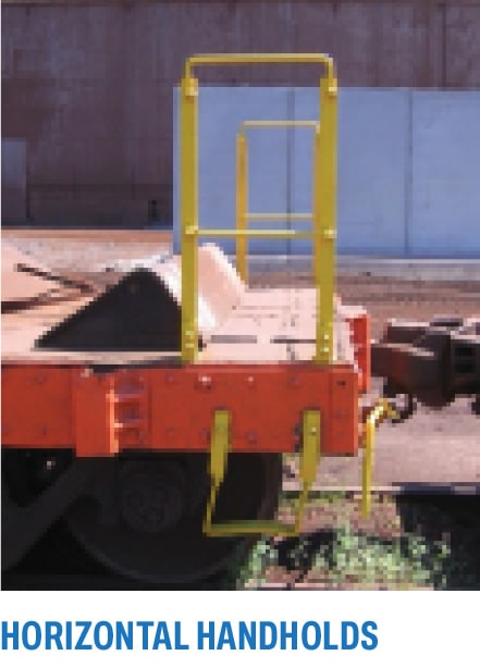
- Only ride flat cars that are equipped with dual vertical handholds or horizontal handholds that extend at least
18 inches above the deck of the car.
Locomotives:
- Do not carry equipment, grips (bags) or other objects when mounting or dismounting a locomotive.
- Place the objects on the deck of the locomotive and climb on or off, using the stairs and handrails, while facing the locomotive.
- Always face the locomotive and use the stairs and handholds when dismounting.
- Do not ride on the steps of a locomotive when traveling over a road crossing.
- Ride in the locomotive cab or on the deck of the locomotive while holding onto the railing.
- Do not ride on the side walkways of a moving locomotive.
Safety Procedure – 10: Coordination of Multiple Train Crews
- When two or more train crews are assigned to switching work in the same yard during the same shift, the preferred method of coordination is for only one crew to be working in the yard at a time. A second crew should begin switching in the same yard only after the first train crew has completed its work and has cleared off the tracks.
- When operational needs require two or more train crews to perform work in the same yard at the same time, the following precautions must be taken:
- Before commencing the switching assignment, all members of all the crews involved in the assignments will conduct a joint job safety briefing [See: Safety Procedure – 1: Job Safety Briefing] to discuss how the work will be performed and coordinated to prevent two or more crews from working on the same tracks at the same time.
- If operational needs require two crews to work on a one- or single-yard track during the same assignment (dual occupancy), all members of all the crews involved in the assignment will conduct a joint job safety briefing and coordinate their work so that only one crew will be working any particular track at a time. This shall be accomplished in the following manner:
- During the initial joint safety job briefing, the crews involved in the work will identify all the tracks subject to dual occupancy, i.e. tracks on which the two crews must work during the course of their assignments;
- Before a crew commences work on any of the identified tracks, they will inform the other crew which track they intend to work on;
- The other crew must confirm that the first crew is commencing work on the identified track and they will remain clear of that track;
- All members of both crews will confirm their understanding that the first crew is commencing work on the identified track and the other crew will remain clear of the track;
- When the first crew has completed work on the identified track, they will notify the other crew they are clear of the track;
- Members of both crews must confirm that the first crew has completed work on the track and is clear of the track;
- This process shall be repeated if either crew intends to work on any of the tracks that have been identified for dual occupancy.
Safety Procedure – 11: Blue Signal and Blue Flag Protection
- Blue Signals include blue flags and blue signal lights. Blue signals designate that on-track equipment is being inspected, tested, repaired or serviced by maintenance personnel, railroad Mechanical Department personnel or contractors.
- Train crew employees and other employees who are not part of the work group that applied the Blue Signal:
- May not go under or on equipment protected by a Blue Signal
- May not enter a track where a Blue Signal is displayed
- May not couple to equipment protected by a Blue Signal
- May not move equipment protected by a Blue Signal
- A blue signal may only be removed by individuals from the work group that applied the blue signal.
- Blue Signal Protection shall be established as follows:
- Each switch providing access to the track where the Blue Signal Protection is being applied must be lined against movement to that track and secured by an effective locking device per company procedures.
— A blue signal must be placed at or near each such switch. - A derail capable of restricting access to the portion of track where work will be performed must be locked in derailing position with an effective locking device and positioned at least 150 feet from the rolling equipment to be protected.
— A blue signal must be displayed at each such derail. - Other on-track equipment must not be placed on a track to which a blue signal has been applied, in a manner that will reduce or block the view of the blue signal.
- Each switch providing access to the track where the Blue Signal Protection is being applied must be lined against movement to that track and secured by an effective locking device per company procedures.
Safety Procedure – 12: Kicking Railcars (Kicking railcars is only permitted per Company procedures)
- Kicking railcars is the practice of uncoupling one or more railcars on the leading end of a shove move, while the shove move is in motion, and allowing the railcars to roll free into a track. Kicking cars is only permitted when it will not endanger workers, equipment, or contents of cars. Kicking railcars may only be performed in accordance with written Company safety procedures developed with workers and their representatives by mutual agreement. The plant manager, area manager and safety manager, must approve locations and procedures for kicking cars. Only employees who have been trained and qualified in the Company’s written safety procedures for kicking railcars may perform kicking moves.
- Before railcars are kicked into any track, a sufficient number of railcars shall be shoved into the track and secured with hand brakes to serve as a backstop to prevent kicked cars from rolling away. The number of secured cars to be used in establishing a backstop shall be specified by company procedures, taking into account the grade of the track and the number and weight of the cars being kicked.
- Company procedures shall establish limits on the number of railcars that may be kicked at one time. However, the maximum number of railcars in any kick move must not exceed four (4).
- Company procedures shall address the speed(s) at which kick moves may be made, considering the grade of the track
and the number and weight of cars to be kicked. - When a train crew is kicking railcars into one or more yard tracks, no employees or personnel should be working in those tracks until all kicking moves have ceased.
- When more than one train crew member is working on the ground while kicking moves are being performed (e.g. one employee operating the cut lever and the other employee operating switches), the employee directing the kick move shall announce, over the radio, the track where the kick move is going.
- Kicking cars over a highway-rail grade crossing or pedestrian grade crossing is prohibited.
Safety Procedure – 13: Coupling and Uncoupling Air Brake Hoses
- Safety Procedures Prior to Coupling/Uncoupling Air Brake Hoses
- Only employees who have been trained and qualified may couple or uncouple air brake hoses.
- Before attempting to couple or uncouple air brake hoses, be sure equipment is properly secured:
- For rail cars attached to an occupied locomotive or other motive power, apply 3-Step (Red Zone) protection. [See: SP-4 3-Step Protection]
- For equipment that is not attached to an occupied locomotive, apply a sufficient number of hand brakes.
- Treat all closed angle cocks as though the train brake line (i.e. airline) is charged with air.
- Coupling Air Brake Hoses
- Step between the cars, placing one foot in the gage of the track and one foot outside the rail, then crouch down (bending at knees and hips).
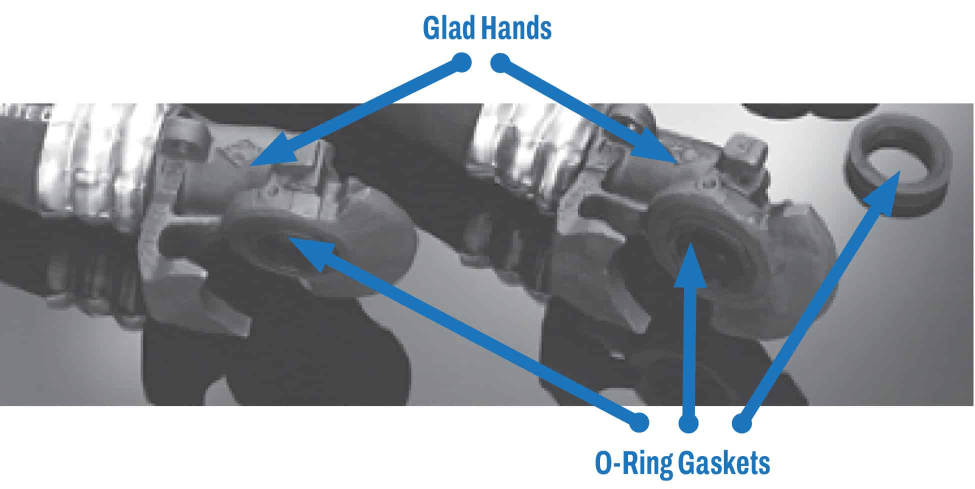
- Make sure that both glad hands have gaskets (i.e. O-rings).
- Grasp the air hose nearest you firmly behind its glad hand and bend it upward.
- Grasp the hose farthest away and pull it toward the bent hose.
- Match the glad hands into opposite contoured slots and push them downward. Observe that the glad hands are seated.
- Gradually open the angle cocks, be sure your head is turned away from the hoses and angle cock.
- Do not reach over the drawbar when opening the angle cock on the other side of the equipment.
- Uncoupling Air Brake Hoses
- The preferred method for uncoupling air brake hoses is to simply uncouple the cars of the train.
Employees should turn their heads away from the air hoses when operating the uncoupling lever (cut lever). - If an air hose or the connection between coupled air hoses is found to be leaking or it is not feasible to uncouple the cars, the following procedure may be used to uncouple the air hoses to make necessary repairs.
- Close both angle cocks and wait until no more air is heard to be leaking from the defective hose or coupling.
- Do not reach over the drawbar to close the angle cock on the other side of the equipment.
- Step between the cars, placing one foot in the gage of the track and one foot outside the rail, then crouch down (bending at knees and hips.) Firmly grasp each air hose with your hand just behind each glad hand.
- Turn your face away from the glad hands. With your arm extended and with quick motion, pull the hose glad hands upwards.
- The preferred method for uncoupling air brake hoses is to simply uncouple the cars of the train.
Safety Procedure – 14: Aligning Couplers
- Only employees who have been trained and qualified may align couplers. Drawbars are heavy and have multiple pinch points.
- There are two primary methods to align couplers:
- Backward Method
- Knuckle-Mate Device
- Whenever aligning a coupler, regardless of which method is used, the following precautions must be followed:
- Separate the cars to be coupled by at least 50 feet;
- Secure the cars by establishing 3-Step Protection to cars attached to an occupied locomotive
[See: SP-4 3-Step Protection] and by setting appropriate number of handbrakes on cars unattached to a locomotive; - Never kick a coupler or drawbar;
- Draw bars are heavy. Do not attempt to lift a drawbar. Get assistance if coupler does not move when moderate force is exerted;
- Keep fingers clear of pinch-points;
- Establish a firm footing.
- Backward Method
- Stand to the side of the coupler;
- Turn your back to the coupler and lean against it;
- Place one foot underneath coupler and other foot in front of you. You may brace your forward foot against the sideof the rail (do not step on top of the rail);
- Grip the coupler from underneath, keeping fingers clear of pinch points;
- Bend your knees and hips while keeping the load close to your body;
- Push upward from your knees with your legs while shifting your weight backward to push the drawbar over;
- Only push a small distance, stopping to reposition yourself as needed;
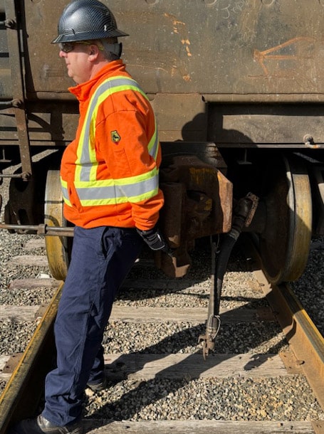
- Knuckle-Mate Device
- Make certain that the knuckle is locked in the closed position with the pin down.
- Connect the knuckle-mate by placing it over the top of the knuckle, making certain the central pin is securely in the hole of the knuckle (the pin may be adjusted by loosening the top levered nut).
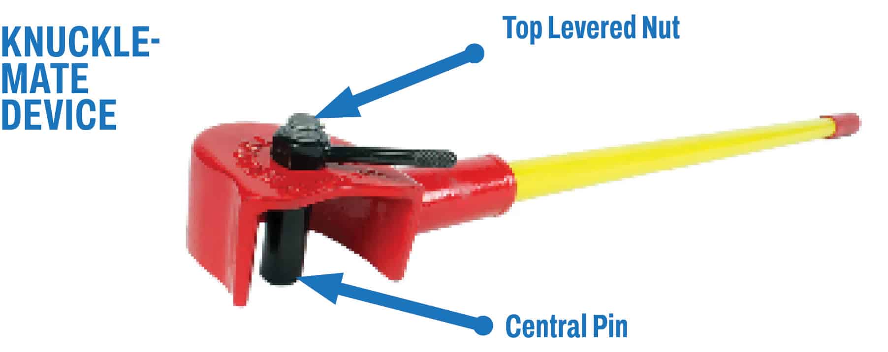
- Assume a balanced position with a wide stance and your center of gravity between your feet. Keep both hands on the handle.
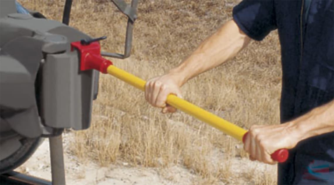
- Adjust the coupler by pulling on the knuckle-mate, using your legs. Be prepared for unexpected movement.
Safety Procedure – 15: Replacing Knuckles
- Only employees who have been trained and qualified may replace knuckles in couplers.
- Protection must be established prior to replacing a knuckle using either of the following methods:
- Establish blue signal/flag protection [See: SP-11 Blue Signal and Flag Protection].
- If blue signal/flag protection is not used:
- Separate the equipment by at least 50 feet;
- Establish 3-Step Protection on equipment attached to an occupied locomotive;
- Set an appropriate number of hand brakes (and wheel chocks, if required by company policy) on equipment that is not attached to a locomotive.
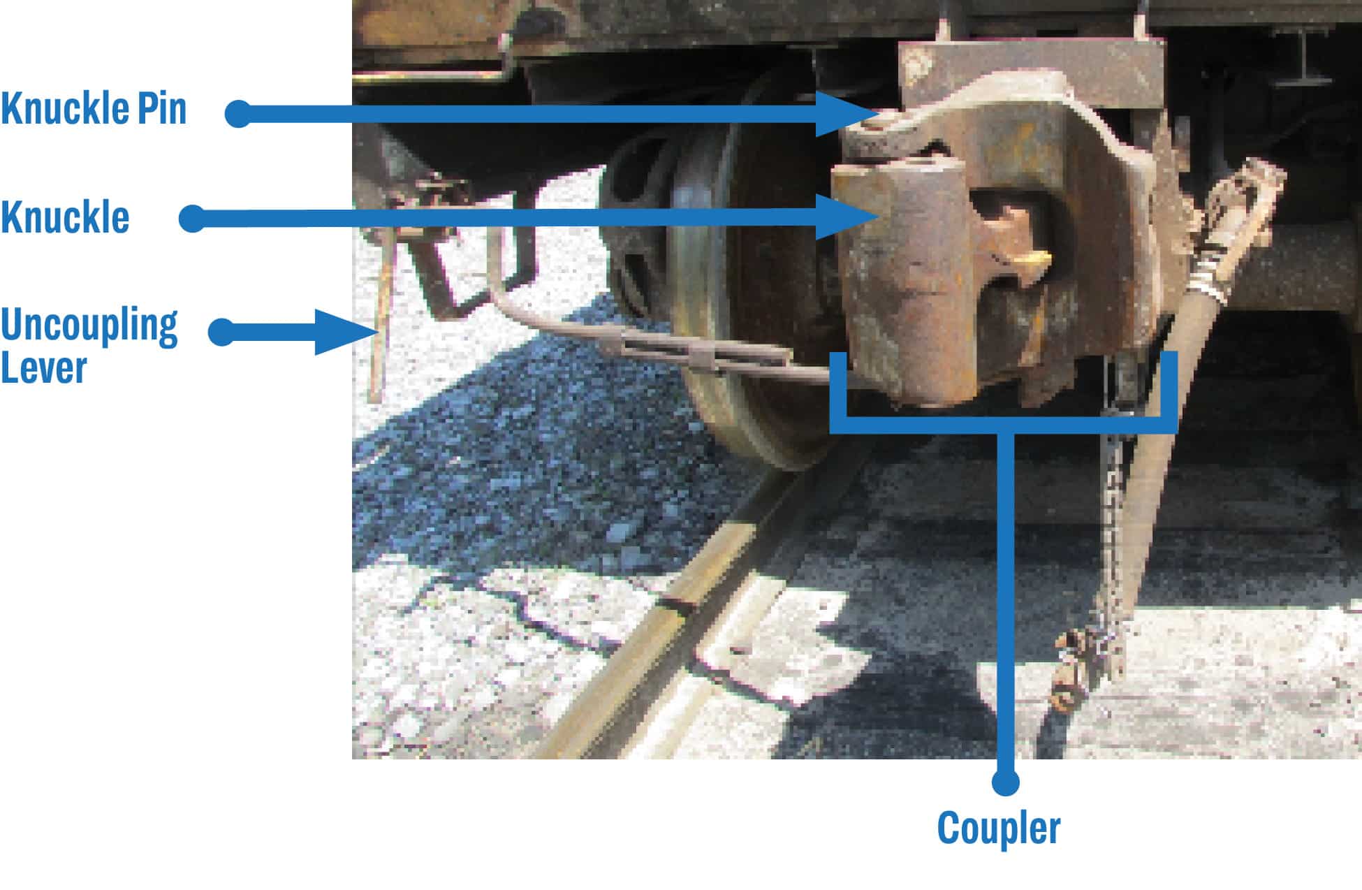
- Procedures for replacing a knuckle are as follows:
- Obtain the correct knuckle type;
- Make sure the knuckle pin is in place and open the knuckle while keeping feet clear of the area under the coupler;
- Using the buddy system, remove the knuckle pin and set it within easy reach;
- Remove the knuckle by operating the uncoupling lever (cut lever) and let the knuckle fall to the ground;
- Dispose of the knuckle where it will not become a tripping hazard;
- Holding the uncoupling lever in the open position (lever up), move the knuckle thrower back into the coupler recess as far as it will go;
- Lift the knuckle carefully and place it into the coupler pocket;
- Insert the knuckle pin into the pin hole, close the knuckle, and make sure it locks properly.
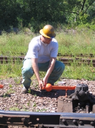
Safety Procedure – 16: Operating Track Switches
- Duties of Conductor/Ground Person
- Before operating a switch, observe that the points are not damaged, and there are no obstructions inside the switch point, or near the switch rods, and the switch has not been spiked;
- Before unlatching the switch lever, move it up and down slightly while still in the keeper to determine if it is free from excessive tension due to mechanics, the environment (including heat), location of equipment, etc;
- Procedures and training must require standing clear of the handle’s travel path to avoid being struck if the lever has excessive tension;
- To operate a switch:
- Hold the lever with two hands;
- Do not bend over to operate the lever. If necessary, bend your knees and lift with your legs, keeping the end of the lever centered in front of you;
- Reposition your body while keeping the lever in front of you to complete the rotation of the lever;

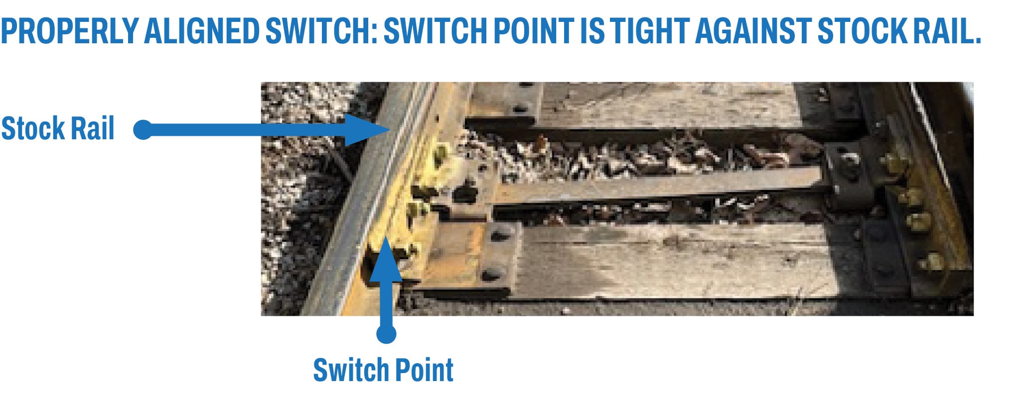
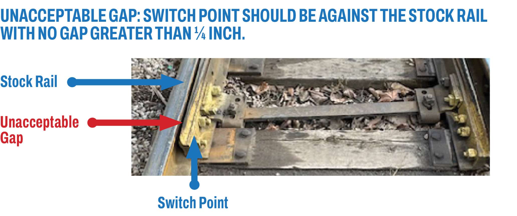
- When the switch movement is completed and the lever is latched in place, visually check the switch points againto determine the point has closed tight against the stock rail.
- If there is gap of ¼ inch or more, try operating the switch again;
- If the gap persists, report the condition to management, and seek instructions
- If there is an obstruction between the switch point and stock rail, use a tool or other object to remove it. Never place your hands or any part of your body between a switch point and stock rail.
- Switch plates shall be periodically cleaned and lubricated to prevent them from becoming difficult to operate.
- Immediately report defective switch conditions to management or proper authority, including switches that are difficult to operate. Remove from service accordingly.
- Duties of Locomotive Engineer/Operator
- When a train stops near a switch to drop off a crew member to operate the switch, it should stop at least 25 feet from the switch points to avoid crowding the switch.
- If a train stops near a switch for a train meet or to be left unattended, it shall stop at least one car length clear
of the foul zone – i.e. the space between the switch points and the foul point for the adjacent track.
- If a train stops near a switch for a train meet or to be left unattended, it shall stop at least one car length clear
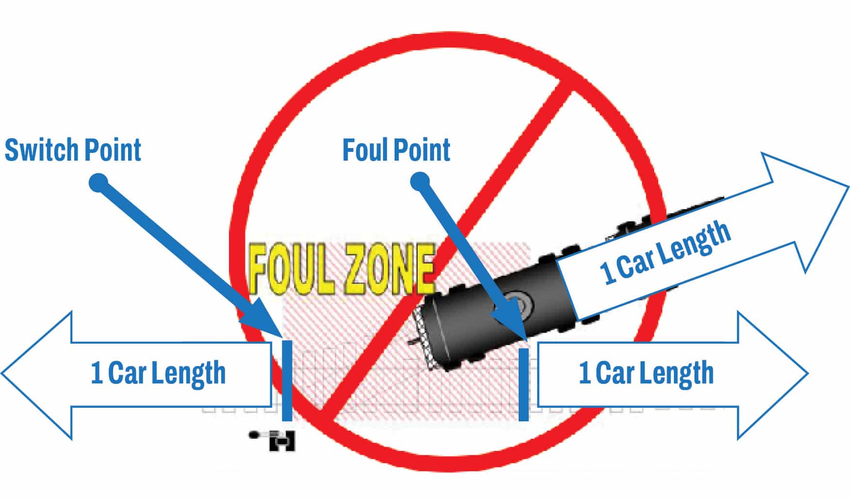
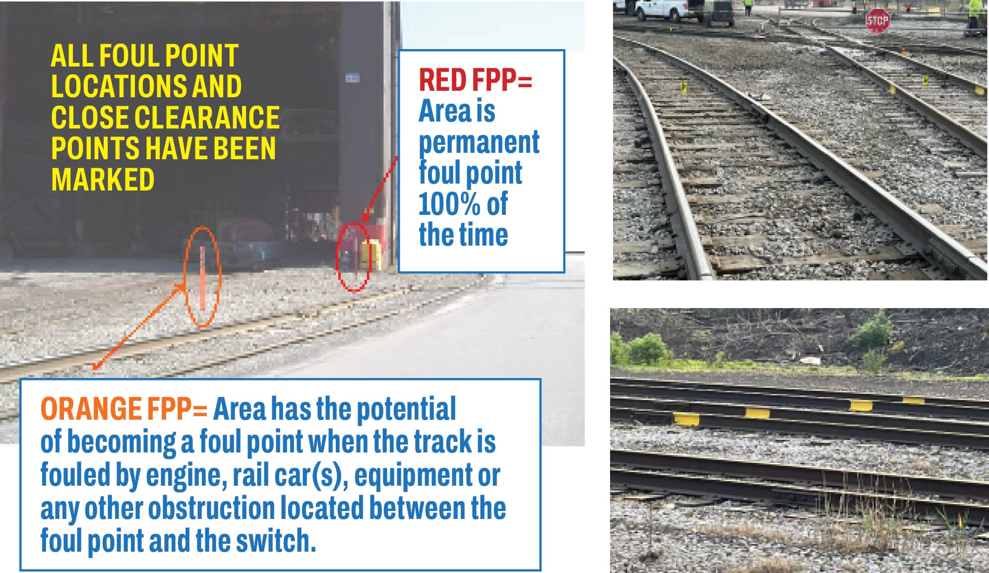
- Marking Foul Points with Foul Point Posts or Visible Markers at Switches and Turnouts
- Based on a risk assessment, foul point posts (FPP) or visible markers must be installed at the foul points of switches and turnouts to warn train crews when they are approaching the limits of a potential close clearances location (foul zones). [See: RP-3 Horizontal and Vertical Track Clearances Policy]
Safety Procedure – 17: Personal Protective Equipment (PPE)
- The company shall provide at no cost, correctly sized and readily available personal protective equipment (PPE). Employees shall be trained to wear the required and approved PPE in accordance with a company’s hazard assessment for PPE, and safety procedures. Approved PPE includes, but is not limited, to the following:
- High visibility clothing of approved colors with retro-reflective strips;
- Hard hats;
- Safety boots with a defined heel per workplace procedure(s);
- Approved safety glasses;
- Face shields;
- Hearing protection;
- Flame retardant clothing (where required);
- Inclement weather clothing (rain, sleet, snow, cold temperatures, etc.);
- Personal fall arrest systems (where required);
- Approved gloves
- When handling railcars containing molten metal or hot metal slabs (heats), flame retardant gloves and clothing shall be worn in accordance with the company’s safe job procedures or job safety analysis.
- The company shall not allow PPE or clothing that is loose, torn or baggy to the extent it can be caught on rail equipment, track appliances, buildings or machinery per procedure(s). Cuffs on overalls, pants, and jacket sleeves shall be buttoned or secured to prevent being caught on projections.
- Training shall be provided to employees in the use, care, and maintenance of PPE.
- PPE shall be replaced when it is worn-out or damaged at no cost to employees.
- A union-management health and safety committee must periodically review/update, and evaluate the effectiveness of the PPE program.
- PPE is the least protective control in the hierarchy of controls. Therefore, hazards must be identified, eliminated/controlled by following the hierarchy of controls.